Skip to the navigation. Skip to the content.
MailASail Roam-Free Communications
  • Home
  • Web Mail
  • Web Diary / Blog
  • Weather
  • Change Your Acct Settings
  • Support
  • View Basket/Checkout

MailASail

  • Home
  • About Us
  • Contact Us
  • Links
  • Press / Testimonials
  • Customer Case Studies

Communications

  • Sat Phone Buying Guide
    • Iridium
    • Inmarsat
    • Globalstar
    • Thuraya
  • Mobile (4G/3G) Internet
  • Wifi Bat
  • RedBox

Shop

  • Buy Online
    • Iridium Satellite Phones
    • Inmarsat Fleet One
    • Inmarsat FleetBroadband
    • Inmarsat IsatPhone Pro
    • Iridium Antennas (handheld)
    • Iridium Prepaid Airtime
    • RedBox
    • Wifi Bat
    • 4G Roam Free Gateway

Services

  • teleport-it
    • Sign Up!
    • Pay Subscription
  • Training and Support Packages

Support

  • Documentation
  • Downloads
  • Remote Support Remote Support
  • Contact

    Unsure what you need?
    Contact us now:

    Address:
    Mailasail
    Unit 8 Saxon Business Centre
    41-59 Windsor Avenue
    London
    SW19 2RR

    Sales:
    email: sales@mailasail.com
    tel: +44 20 70432832

    Support:
    email: support@mailasail.com

    Follow us:
    Facebook
    Twitter
    Instagram

    Iridium Certus Thales VesseLink Power

    Home » Documentation Home » Iridium Certus Thales User Manual » Iridium Certus Thales VesseLink Power 

    The Thales VesseLINK (200 & 700) requires a 12V or 9-36V power input and can be powered via two main options:

    Power from mains 110/240V AC "brick"

    The Thales VesseLINK (700 terminal) comes with a mains AC adaptor which will convert various mains AC to 12V. This is connected via the circular connector on the Thales base unit (this is an optional add-on for the VesseLINK 200 terminal)

    Power from DC or battery input

    Both VesseLINK terminals (200 & 700) can also be powered from a battery 10-32V input. This will be connected via the D shaped connector and requires an additional cable not supplied with the standard retail box.

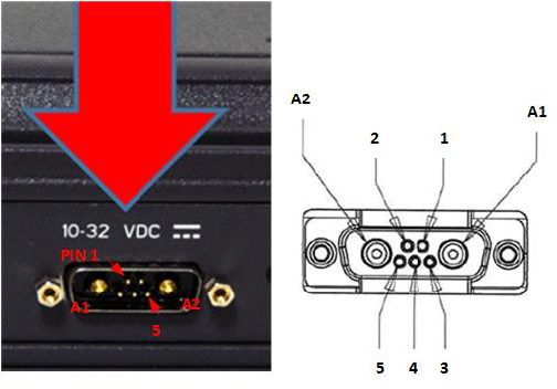
    • Positive and negative DC are connected to the two large connectors
    • An "ignition" input also allows the unit to be auto powered up/down using an external cable. This is not mandatory and the alternative is to power on/off using the switch on the front of the BDE (or disconnecting main power).

    Wiring diagram:

    • A1 = V+ /10-32VDC
    • A2 =V- /GND
    • Pin 5 = Ignition

    More info:

    • Iridium Certus Thales VesseLink Installation Guide
     
    • Home
    • Web Mail
    • Web Diary / Blog
    • Weather
    • Change Your Acct Settings
    • Support
    • View Basket/Checkout

    If you would like to know more about these services, would like to arrange a trial of the email compression, or just have a general question about email on yachts, then please drop us a line at: info@mailasail.com


    General Terms and Conditions - Site Terms and Conditions - Other Terms and Conditions - Privacy Policy? - Copyright(c) 2002-2022 MailASail